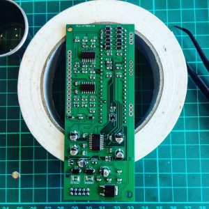
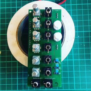
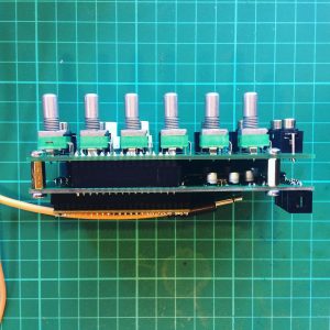
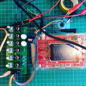
For the past few months (yes, it’s a slow process), I’ve been working on a new version of my Teensy based eurorack boards. Whereas my previous boards have used either the Teensy’s built-in ADC and DAC, or the PJRC audio shield, this one uses a separate chip, known as an audio codec, called the WM8731, to perform these duties. The benefits are increased audio quality over the built in ADC/DAC, without the need of the more expensive, and physically large, audio shield. It’s been a bit more challenging than I expected. The first PCB prototype I had made had a number of issues with it. Some were just careless mistakes, others originated from a lack of understanding of the WM8731, and how it uses I2C and I2S protocols. My first board is a mess of soldered on wires and extra resistors to fix issues. It was a useful learning experience, and allowed me to fix the errors and produce a new PCB. Today though, I finally got everything working.
The main difficulty was that debugging digital chips is hard. If you don’t set everything up correctly it just doesn’t work. Then you’re left scratching your head trying to get to the root of the issue. Is it the circuit that’s wrong? The soldering? The code? Did I burn out the chip when soldering? This meant the whole process took a long time. Also, the chip is SMALL. It’s 0.5mm pitch which is quite tricky to solder by hand. This is my first fully SMD board, so I’m a bit of a novice with SMD. Most of the other components where fine, but this one was a real pain. I tried ‘drag soldering’ which people say is ‘easy’, but I found I just bridged all the legs together. So I opted for slowly and painstakingly soldering each leg, accompanied with copious swearing!
I’ll post more details on this as I develop it. First job is to port my current effects to this board, and incorporate 6 CV inputs. Finally, I’ll be able to make use of one of the main advantages of modular!


