Tag: diy

  • AudioFreeze Fascia complete

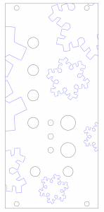
    To be able to mount my AudioFreeze PCB in a modular case I needed to craft a fascia. I decided to use laser-cut acrylic. I haven’t found anywhere in the UK that does bespoke Aluminium cutting, and, due to a kind friend, I had access to a laser cutter! I created a vector image in InkScape, a free, well-featured vector art package. It does have its drawbacks though, it’s not particular user friendly. I haven’t found an easy way to show the centre of objects, so I ended up making guidelines to show me, and hiding them in another layer.

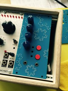
    I came up with a design involving snowflakes, and I wanted these to be in a different colour. I covered the acrylic in masking tape, and once it was cut I painted over the top with several layers of thin acrylic paint. It wasn’t entirely successful, the paint didn’t fill the etched areas quite as well as I’d hope, but I’m still very pleased with the final result. One downside of using acrylic is that it’s 3mm thick, which seemed slightly too deep to be able to get a nut on the jack sockets as not enough of the barrel protruded. The Aluminium panels from the Thonk – Music Thing kits I’ve built were thin enough not to have this problem.

    I’ll make another demo video soon..
     

    Screen Shot 2016-06-18 at 18.47.58
    Vector image for laser cutting


    IMG_0573
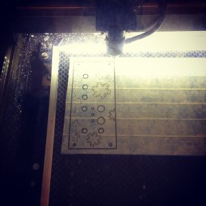
    Laser cutting the masking taped acrylic


    Painting onto the fascia
    Painting onto the fascia


    IMG_0576
    Finished article!
  • AudioFreeze Prototype built

    After a few hours of soldering my PCB is populated and it works! There was no way of knowing for sure without building it, and as this was my first PCB I had some doubts, but thankfully it’s all good. The LEDs and corresponding resistors have yet to be added, I wanted to wait for the facia before soldering these in place to get the height right  It can be powered either via USB or from the 5V line on the Eurorack connection.

    First version of the firmware is up on GitHub. Current version has only one mode. Top red button captures a loop of audio. Pots from top to bottom control:-

    • loop window size
    • loop window position
    • pitch
    • mix with incoming audio

    Bottom red bottom currently doesn’t do anything, but my plan for the next version of the firmware is to have multiple modes. I’m thinking of a mode which has a volume based threshold for triggering the sampling, and possibly a granular delay mode. Also the ability to sample in 8 bit (rather than 16 bit) for increased loop time. LEDs are also unused currently, they will probably show active modes.

    Next up is the fascia, hopefully laser cutting that this week so expect pictures soon.

    A photo posted by @scottpitkethly on

    A video posted by @scottpitkethly on

  • MIDI Controller Stage 2

    It works! I had made a couple of foolish errors, due to looking at the wrong pin schematic for the TEENSY (I have 3.2 not 2). But I now have a working, single pot controller. With this mastered I’m hoping that adding more pots should be straight forward. I’d also like to include an LED that flashes on the MIDI clock, this should help me keep time without the need for headphones.

    I was impressed at the simplicity of the coding for TEENSY. The snippet below is the entire code. I’m having to smooth the value to reduce noise. Apparently the inclusion of a capacitor will help reduce this.

    Looking forward to designing a case..


    #define NUM_PORTS           1
    int values[NUM_PORTS][2];
    
    void setup()
    {
    
    }
    
    void loop()
    {
    
     for( int i = 0; i < NUM_PORTS; ++i )
     {
       const int prev_value    = values[i][0];
       const int current_value = values[i][1];
       int new_value           = analogRead( A0 ) / 8;
    
       int blended_value       = ( new_value + current_value + prev_value ) / 3;
    
       if( prev_value != blended_value )
       {
         Serial.print("analog 0 is: ");
         Serial.print(blended_value);
         Serial.print("n");
    
         usbMIDI.sendControlChange( 1, blended_value, 1 );
       }
    
       values[i][0]             = current_value;
       values[i][1]             = blended_value;
     }
    
     delay(5);
    
    }
    
  • MIDI Controller Protoype

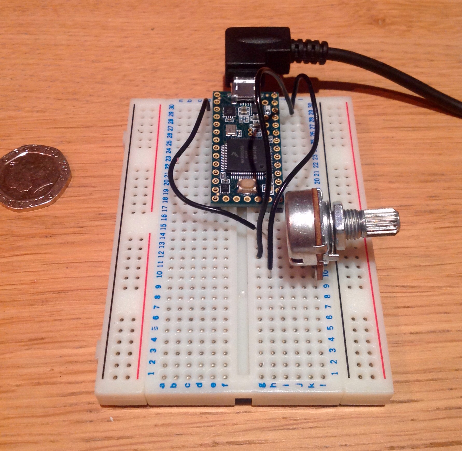
    I’ve just put together a very simple prototype for a USB MIDI controller. I’m using Teensy, which is a programmable circuit board, which lets you code small programs in C, and upload them to the board. Very much like Arduino, but smaller, and easier to setup MIDI on. I’ve just prototyped it on some breadboard. Once I’ve got a setup I’m happy with I can start on the enclosure. It’s not working quite right yet, more details to follow.


  • DIY controllers

    When I began to prepare to play live, earlier this year, I was amazed how few decent USB MIDI footpedals were available. Especially ones small enough to fit in my gig bag. As an aside, after spending ages in previous bands, lugging and setting up gear, one of the tenets of Cutlasses was to have a live act that ostensibly fits into a single bag (plus my guitar). It strikes me as strange that there isn’t a 4 switch, programmable USB pedal, around the size of those larger EHX pedals, widely available. There is Looptimus, but that’s rather expensive and over-customisable for my needs. Another thing that struck me as strange was that the vast majority of information online about such pedals was from people playing music at church congregations. Am I really the only electronic musician who wants to use their feet as well as their fingers? (I realise I’m not.) My eventual solution was to buy a homemade non-programmable USB 4 switch midi pedal from eBay (pretty cheap, sub £50), and replace the DPDT switches with the combination of toggles and latches that fitted my needs.


    I found this very slight foray into the world of soldering and DIY controllers pretty fascinating, so I’m going to try and take it further. I’m considering for my next project, building something from scratch using the TEENSY USB development board, more on that if and when it happens.