Tag: eurorack

  • Developing on STM32

    Over the past months I’ve been investigating moving away from Teensy to another microcontroller  ecosystem. I love Teensy, and I wouldn’t have made the majority of my projects without it, I’ve learnt so much from it, and I still think it has the best libraries of any of the alternatives. It’s always the first thing I recommend to get people started on doing digital audio electronics and I’m sure I’ll use it again in the future. But, it has a few, in my opinion, major downsides, once you get a bit more advanced.

    Development Environment – Teensy uses the Arduino IDE, which is fine for writing small programs to flash leds, read sensors etc, but is a little basic for larger scale projects.

    Debugging – This is the big one for me, Teensy doesn’t provide a method for debugging (other than using Serial Monitor). I’ve spent literally hours trying to debug audio glitches that would have been relatively straightforward to find if I could just set a breakpoint and step-through. I have seen people exposing the JTAG pins on the Teensy and using these, but I wanted something supported by the vendor.

    Manufacture – If you want to do a manufacturing run of your project with Teensy you have 2 options. Either mount the Teensy itself on the board, which can become quite expensive if you’re doing more than a couple, or buy the bootloaders directly from PJRC and use the specific microcontroller to match the Teensy. I wanted to be able to make small runs of my boards (still less than 10), without the expense of buying many Teensy’s, and choose a chip specific to the needs of each project.


    STM32

    After chatting with Alex Evans, (mmalex on Twitter), who had already started working with the STM32 range of microcontrollers, I decided to check them out. They have a huge range of chips, ranging from arduino level all the way up to Teensy 4 capabilities. The Eclipse based IDE supports debugging, and they are fairly easy to include in your schematic (requiring a bunch of power-filtering caps but not much else.)

    STM make their own range of dev boards, similar to Arduino and Teensy, called Nucleo. There are lots of them, and it takes a while to filter through the STM range and find the chip and associated Nucleo you are looking for. They’re very reasonably priced (I suspect they are sold as a loss-leader) and are the best way to get started. They have a fairly large form-factor, so it’s unlikely you’d want to include them directly in your project, like you would a Teensy. But they are perfect for experimenting with the hardware before you start on your own PCB.

    I strongly recommend checking out mmalex’s youtube channel, where he has live streamed a series of videos explaining how to get into STM32 eurorack module design. They are super informative and well worth watching. Also this series by DigiKey on getting started with STM32 is essential viewing if you are interested in developing with them.

    STM32CubeIDE

    First experiences with the IDE weren’t great, unfortunately  it’s plagued with a number of small bugs and glitches. It really didn’t like me working in C++ and kept defaulting my project to C, which I then had to unpick in the project settings each time. Actually that bug has been fixed, and it does seem to be slowly improving, although each new update seems to introduce some fun new issues. It works ok-ish though, it’s free to use, and I can FINALLY debug!

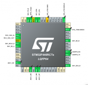
    The work-flow involves using the IDE to visually configure your chip, you can set which peripherals you want to use, and which pins to connect them to. This will then generate (lots) of code, which basically sets the correct registers to initialise the peripherals and provides you functions to use them. They use something they call HAL (Hardware Abstraction Layer), so that the functions look the same regardless of what underlying chip you are using. Beware though, I’ve heard that different chips seem to have their own foibles in terms of setup, and some of the code requires manual tweaking. I’m using an F446, and so far, the generated code seems to be fine.

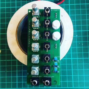
    Once this code is generated, you can start adding your own code. Any code added in the auto-generated files needs to exist between specific comment lines that the generator marks out for you. My first project was a PCB which connected the STM32F446 to a WM8731 audio codec, was powered by eurorack +12/-12V, and broke out many of the STM32 pins onto header. The intention is that this board will be coupled with another (module specific) board, which will add interface components (pots, jacks etc) and route them to the breakout pins. You can see the code here which initialises the STM32 and configures the WM8731 via I2C.
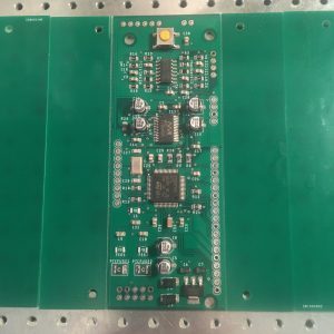
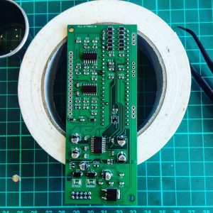
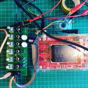
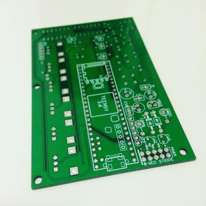
    The SMT32 board with solder paste applied and components placed ready for the reflow oven.


    I’ve just sent out some gerbers (PCB files) for manufacture, I will hopefully have them in a week or so, so look out for more news on my latest module!

  • Looper Version 1 Complete

    If you’ve been paying attention to this site, you’ll have seen I’ve been working on a eurorack looper for sometime. The first version of this is now done. You can find the source code here.


    What is it?

    A looper module in the eurorack format inspired by the MLR app which ran with the monome. It records audio to an SD card, so is not limited by RAM constraints. It supports unlimited overdubs, only limited by headroom (e.g. if you layer over too many overdubs, the audio will begin to digitally clip). Once the loop is recorded, you can switch from Record Mode to Play Mode. This allows you to ‘cut’ the loop using the 8 buttons. Each button will jump to a section of the loop, essentially dividing the loop into 8 equal size segments.


    How does it work?

    The version shown in this video uses Version 2.0 of my Teensy 3.5 based audio board. This uses the in-built ADC and DAC to process audio. The audio is recorded to SD card. As SD cards are rather slow, especially when writing, I need to use 2 circular buffers. One for reading audio, and one for writing. SD cards are slightly unpredictable in terms of read and write speed (e.g. writing the same size block can take varying amounts of time each time you do it), I had to experiment to get buffer sizes that worked. These may need to change when using other SD cards.

    I achieve overdub by keeping 2 copies of the audio loop, whilst one is being played, the other is being written to. At the end of the loop, the files are swapped (read file becomes write file and visa versa), and the loop starts again. When the Record button is pressed again, to engage overdub, the incoming signal is added to the recorded signal, and written to the write file.

    I designed a separate PCB to deal with the 8 LED buttons. This communicates with the Teensy via I2c. The code is here. It uses a technique borrowed from the Le Strum by 64pixels which uses a shift register to scan the buttons and turn the LEDs on and off. Take a look at this schematic to see how it’s setup. Essentially a single bit at a time is shifted all the way through the 8 bit shift register. Each output of the shift register is connected to the LED and the switch of one of the buttons. So the single ‘bit’ will visit each of the buttons in turn. For each button we can read the value of the switch (is it pressed or not), and decide whether to turn on the LED or not (this is done by turning on the transistor). This is done very quickly, so you can give the impression a button is continuously lit, even though it is actually flashing on and off very fast.


    What’s next?

    I’m already working on Version 2 of this looper. I’ve split the buttons out onto a separate module which I plan to mount horizontally in the 1U section of my eurorack case, to save space in the 6U section. Features of the upcoming version 2 are.

    • Separate audio codec (WM8731) for improved sound quality,
    • CV control of the module, will allow for gates to control loop position, as well as controlling some of the functions mapped to the dials.
    • Option pedal input so you can record without having to press the button.
  • Case and new module finished

    Nothing is more motivating than an imminent deadline, and my gig in Berlin served as a good end point to get my new case finished, and a brand new module into it.

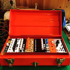
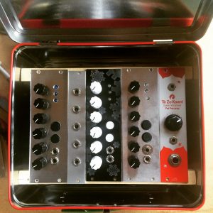
    The case was built out of a Habitat trunk, see more details here. I’m pretty pleased with how it turned out. It’s nice and light, and hopefully pretty sturdy. It survived the flight back from Berlin anyway.


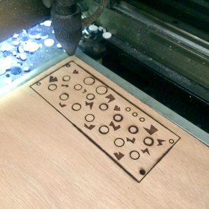
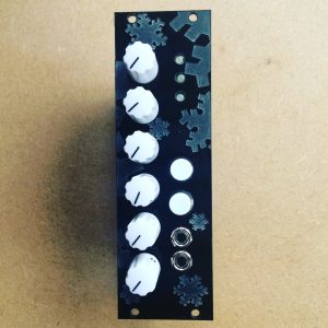
    The new module is actually just a re-working of the GlitchDelay, but it’s using the new PCB I’ve designed. Which uses Teensy 3.5 (again) coupled with an external WM8731 codec (for reduced noise), and has 6 buffered CV inputs. It’s all SMD to keep the size down. The idea is that I’ll be able to produce different front panels, for different module functionality, but keep the back panel the same. I laser cut a panel on ply-wood for the first time. The contrast between the etched and non-etched material is much higher than with the acrylic, which I like.


    Next on the agenda is to modify the case to squeeze a row of 1U modules in. Ideally I can just use this case, with external noise boxes/instruments when playing out live.

  • DIY case almost ready..


    Happy Easter! I’ve spent my time off crafting a DIY case to house the modules I’ve been building. As I’ve been trying to perform using only DIY instruments and effects I’ve built myself, then as Jedi must craft their own lightsaber, it seems fitting I should create my own case. Actually, I already have my Chilli Box case, but I’ve rather outgrown it, size-wise.

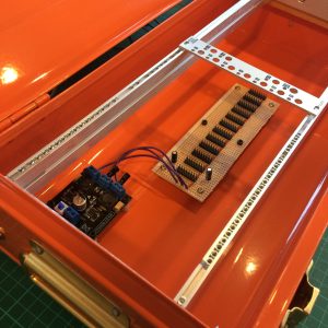
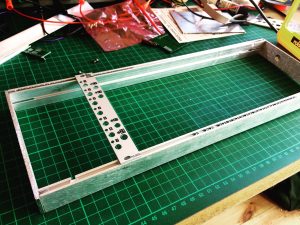
    The case is based around a Habitat trunk which I got in the sale. I used aluminium rails from Mouser, which I set M2.5 nuts into. I cut these down to the correct length with a hacksaw. These were then mounted onto an aluminium mounting frame from Thonk. The frame went together ok, although, getting the supplied bolts to cut a thread into the aluminium rail was a bit tricky, and I managed to rather chew up the head on one of the bolts. Hopefully I don’t need to get that out again!


    The trunk case has a lip all the way around so I ‘plugged’ this by screwing a block of wood on each side, flush with the lip, that I could then mount the frame into.

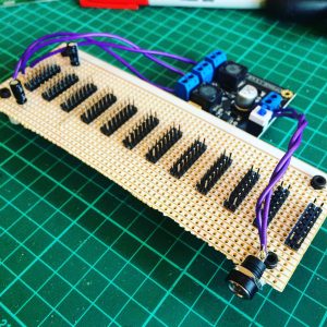
    The power supply was just a cheap Chinese board from eBay (TPS5430), that I added a couple of extra filtering capacitors to, and then used Vero board to mount header to for the ribbon cabled to connect to. The filtering caps were 100uF and 10uF, chosen more due to what was on hand than by any form of science.


    Still need to mount and test it with all my modules, let’s see what new and exciting problems that brings..

  • Fun with audio codecs

    For the past few months (yes, it’s a slow process), I’ve been working on a new version of my Teensy based eurorack boards. Whereas my previous boards have used either the Teensy’s built-in ADC and DAC, or the PJRC audio shield, this one uses a separate chip, known as an audio codec, called the WM8731, to perform these duties. The benefits are increased audio quality over the built in ADC/DAC, without the need of the more expensive, and physically large, audio shield. It’s been a bit more challenging than I expected. The first PCB prototype I had made had a number of issues with it. Some were just careless mistakes, others originated from a lack of understanding of the WM8731, and how it uses I2C and I2S protocols. My first board is a mess of soldered on wires and extra resistors to fix issues. It was a useful learning experience, and allowed me to fix the errors and produce a new PCB. Today though, I finally got everything working.

    The main difficulty was that debugging digital chips is hard. If you don’t set everything up correctly it just doesn’t work. Then you’re left scratching your head trying to get to the root of the issue. Is it the circuit that’s wrong? The soldering? The code? Did I burn out the chip when soldering? This meant the whole process took a long time. Also, the chip is SMALL. It’s 0.5mm pitch which is quite tricky to solder by hand. This is my first fully SMD board, so I’m a bit of a novice with SMD. Most of the other components where fine, but this one was a real pain. I tried ‘drag soldering’ which people say is ‘easy’, but I found I just bridged all the legs together. So I opted for slowly and painstakingly soldering each leg, accompanied with copious swearing!

    I’ll post more details on this as I develop it. First job is to port my current effects to this board, and incorporate 6 CV inputs. Finally, I’ll be able to make use of one of the main advantages of modular!


  • Piano Music

    In the run up to Electromagnetic Field Festival which I played earlier in the year, I was preparing for a performance using only instruments and effects I’d built myself, either from kits or of my own design. The problem was, most of my modules are effects, they transform sound, but they can’t really generate sound from nothing. I had an idea to make a module which would just play piano sounds controlled by CV and gate. Here’s a video of the performance, similar to the one I played at EMF.


    The Piano Player module

    I decided to base the module on Music Thing Modular’s Radio Music/Chord Organ module by Tom Whitwell. It already has inputs for CV and Gate, and is Teensy based, which I’m well versed in. Time was limited so I didn’t want to have to build the hardware as well as write the software. I ordered the module from Thonk as well as a Penrose Quantiser, although I didn’t have time to build this in the end, so ended up doing the quantising in software.

    The Teensy 3.2 has fairly limited memory (64k ram, 256k flash), so I only had space for a single piano sample, which is stored in the flash memory. I then had to write the code which could play this sample back at any pitch, using cubic interpolation to smooth the resulting sound. I wanted the module to have polyphony, so the sounds could overlap, without cutting off the tail of the previous sample. The Teensy 3.2 doesn’t have a floating point unit. This means it has to emulate all floating point (fractional numbers) in software, which is very slow. Initially I struggled to achieve multiple voices at once due to poor performance. I solved the problem by writing a fixed point maths library. This replaces floating point maths calculations with integer based ones, which are faster. You do accrue some loss of accuracy doing this, but it was almost x10 faster, and I was unable to hear any artefacts. This extra boost in speed gave me enough remaining CPU power to add reverb, using the freeverb algorithm in the Teensy audio library. See the source on GitHub for more details.

    In this video, the Piano module is being fed random voltages from the Turing Machine (also from Music Thing). I then quantise this signal internally in software to be in the key of C. Once I’ve built my hardware quantiser I can remove this step. Theoretically this module could play any sample, the sample just needs turning into a .h include file which can be included in the source of the project. I created this using wav2sketch. If you want more samples, or larger ones, you’d need more memory. A Teensy 3.5 could be used to achieve this (as I use in some of my other modules). It does look like you could physically fit this onto the Radio Music board, the only problems I can see might be power related issues, such as discussed here http://www.cutlasses.co.uk/tech/redux-the-redux/


  • The Teensy Trio

    I’ve now built up 3 modules based on my Teensy eurorack board. It was recently discovered that the Teensy 3.5 actually has 256k ram (I think previously it was stated as having 192k?). The latest version of Teensyduino (1.42) unlocks this, so the 3.5 will probably be my goto Teensy board for the near future, as processor speed seems ample to run the effects I’ve written so far.


    The three firmwares featured are:

    GlitchDelay – 4 glitching read heads on a delay line

    AudioFreeze – freeze sections of audio and adjust playback speed, with tape wow/flutter effect

    KhronoKrusher – lo-fi delay


    The KhronoKrusher is the only module which I’ve not mentioned on here before. This one makes extensive use of the Teensy audio library effects, including the new Freeverb effect which came in Teensyduino 1.42. It’s basically a delay -> reverb -> bitcrusher effects chain. It turns out 6 dials wasn’t enough to set all the parameters, so I added what is referred to in the code as ‘push and turn’ e.g. holding down one of the buttons and turning the top knob alters secondary parameters.

  • Redux the redux

    I’ve had a couple of interesting comments on my AudioFreeze/Glitch Delay module which have contributed to revising the PCB, details of which can be found here.

    1. Why is it so big? Good question! The original AudioFreeze is pretty wide, and that’s because the PCB itself is pretty much that wide. I set out to create a smaller PCB.
    2. Why not use the second ADC on the Teensy 3.6 instead of the separate PIC chip? Well, mainly because I’d missed the fact that it had 2 separate ADCs, but I’d been led to believe that this was not possible by people on the Teensy forum, it turns out it is possible, but it’s not totally straightforward.

    Here’s the finished, reduced size module


    Reducing the size of the PCB

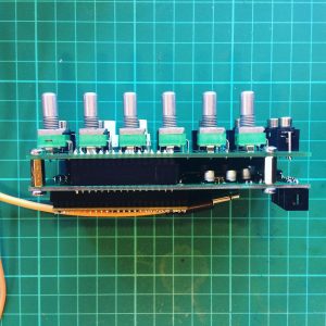
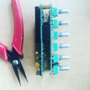
    Getting rid of the PIC chip reduced the number of components, which meant the PCB could be smaller. Also, I split the module into 2 PCBS. One which has the Teensy on and the audio and power circuits, the other has the interface, the pots, jacks and buttons. The PCBs stack, separated by header and copper spacers.


    Removing the PIC chip

    The previous version of the board employed a PIC chip to read all of the potentiometers and pass the values back to the Teensy via I2C. It transpired it was possible to achieve this all on the one board, see here for source code. The ADC library for Teensy allows you to access the 2 ADCs on the 3.6 individually. There are currently a couple of issues with this in the Teensy libraries. One of them is that it’s very important the ADC is initialised before the Audio Library (see struct IO – this enforces initialisation order). Secondly, the Audio Library runs at a reference voltage of 1.2V. Because the potentiometers are connected to the 3.3V line, you need to set a different reference voltage for the 2nd ADC. There is functionality to do this in the ADC library, but it doesn’t work (for a couple of reasons, which I’ve raised on the Teensy forum here). I fixed this by setting the registers directly (see set_adc1_to_3v3())


    Power issues fixed!

    The previous board also had issues where it just wouldn’t start up when connecting to certain power supplies. It turns out, this is due to the time it takes for the 12V line to stabilise. If it takes to long, the 5V line won’t be at 5V whilst the Teensy boots, and it crashes. This explains why, if I powered the Teensy over USB and Eurorack power, then removed the USB, it solved the problem, although felt like ‘jump starting’ it, like an old car! Thanks to the Teensy forum and BCP Music for this information. The solution was to use a voltage supervisor (MIC803). The keeps the Teensy in ‘reset’ until the supply has stabilised.


    So far I’ve made up 3 of the PCBs, all running different firmware (shown here in a DIY case, with a combination of aluminium and laser-cut acrylic panels).


  • Glitch Delay – How it works part 1

    The Glitch Delay is the Teensy based eurorack Delay module I designed that you can read more about here. The video shows what it sounds like, but I thought I’d go into some more detail about how it actually works, and how I went about designing it.

    The Hardware

    The brain of the module is the Teensy 3.6. The code running on the Teensy uses the Teensy audio library, and implements a new AudioStream. Because the in-built ADC of the Teensy is used by the audio library, we need another way to read the potentiometers, this duty is performed by the PIC. The PIC reads the pots and communicates the values to the Teensy via I2C (a well supported and fairly simple protocol for inter chip communication). Op-amps are used on both the input and the output to scale voltages up and down. You can find the complete schematic here, but I’ll go into detail on the major sections below. Many elements of this schematic are cribbed/stolen from other open source schematics. I’d highly advise checking out the circuits behind the Music Thing and Mutable Instruments modules whose schematics are all up on GitHub. I’m a relative beginner when it comes to electronics, so it’s highly likely there are elements of this schematic that are not best practice or wrong in some way, feel free to email me with feedback and corrections!

    Audio input/output

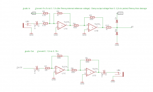
    Audio schematic

    Audio In

    The purpose of this section of the circuit it to scale the modular audio signal from (-5V to 5V), into (0 to 1.2V). 1.2V is the voltage of the internal reference in the Teensy. 5V is added to the incoming signal to bias it to be 0V and above. This circuit is an op-amp summing amplifier similar to this.

    When Vin = -5V
    Vout = ( -(5/8.3) + (-5/8.3) ) = -1.2V (approx)
    When Vin = 5V
    Vout = ( -(5/8.3) + (5/8.3) ) = 0V

    As you can see, this has inverted our signal (the op-amp is in an inverting configuration), so the second op-amp inverts it back again with a gain of 1 (e.g does not change the magnitude of the voltage, it simply inverts the signal)

    Audio Out

    On the way out we want to do the exact opposite. Scale from (0 to 1.2V) to (-5V to 5V) this is achieved using a simple inverting op-amp.

    The gain of the circuit is:
    Gain = -(Rf/Rin) = -(100/12) = -8.3
    Max voltage from Teensy = 1.2V
    1.2 * -8.3 = -10V (approx)

    As you can see, this inverts our signal, so the signal is passed through another inverting op-amp with gain 1. The output of this chain will be (0V to 10V) (actually 9.6V, because we are limited by available resistor values). There’s no need to bias, the output capacitor AC couples the output, blocking direct current. Meaning the output signal is centred around 0V, and therefore (-5V to 5V) again.

    I found the power line to be quite noisy. I tried using an external voltage reference, instead of the 5V power from the regulator but didn’t notice much improvement. Everything is fine if the gain-staging is sound. However, with very low input volumes/voltages you will hear noise when you amplify the output. In future I would add a trimpot or panel pot to adjust incoming voltage (e.g. R1).

    Teensy

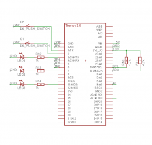
    Teensy schematic


    The Teensy’s main duty is to do the audio DSP. It is connected to the PIC chip via I2C. This uses the SCL and SDA pins on the Teensy (with pull-up resistors to the power line). See here for more information. On the Teensy this is supported through the Arduino Wire interface, and is very straightforward. I shall go into more details on the software running on the Teensy in future posts. The Teensy also controls the LEDs and reads the push switches. There are lots of pins on the Teensy, so it seemed best to connect them here. It could have been done with the PIC, but there aren’t enough pins so you’d need to use a multiplexer.

    PIC chip

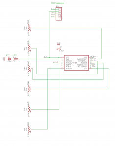
    PIC schematic


    The PIC chip is connected to all the potentiometers. It reads their values and passes the data to the Teensy via I2C. I’ve connected the programming pins to header so it can be programmed on the board. There’s also a connection for an LED for debugging purposes. Neither of these are strictly necessary, but are very useful at the prototyping stage. The capacitor to ground on the power line is as per the data sheet, presumably to deal with minor fluctuations in voltage.

    PCB design

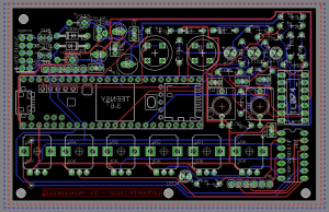
    All of this was designed in the free version of Eagle. A very powerful, but rather infuriating piece of software (the UI leaves something to be desired, although is getting better). After you’ve designed the schematic you have to layout the board. This is a fun and at times tricky puzzle game. You need to route all of your connections without crossing over another track on that layer. You can use vias to change to another layer of the board which makes things easier. It’s definitely worth spending some time experimenting to get a layout you are pleased with. You’ll end up with something that looks like this.


    Glitch delay board layout


    You can then send it to a PCB fabrication house to get it made. I used Hackvana, who I was very pleased with. There are a number of alterations I would make on a future board, a major one being that the power connector is too close to the Teensy, meaning I have to improvise a little on the connections. That said, it did work first time, which isn’t bad for a board of this complexity.


    In further posts I shall go into a bit more detail about how the software works, and further developments.

  • DIY Sriracha Eurorack Case

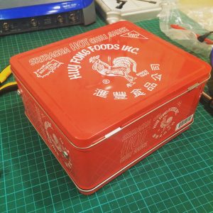
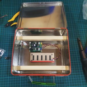
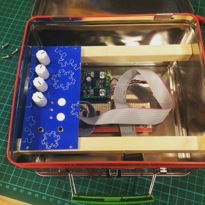
    This weekend I built a DIY Euroack case out of a cheap tin lunchbox from eBay. I want this case to house some of my Teensy based modules and form an all-in-one guitar focused effects box. The project was reasonably straightforward. I used one of these power boards which supplies +12v/-12V from a 14-24V DC power supply. The board that the ribbon cables connect to is vero board with single header, doubled up. Everything was mounted using 11mm M3 brass stand-offs. The wooden rails are possibly a little thick and will limit the size of the PCB under the module panel. Will have to see how that goes. Putting in thinner rails should be feasible. All holes drilled with my new pillar drill. Much easier, with far less swearing than trying to use a standard power drill. The overall project build cost was around£20. Looking forward to filling this with my DIY modules!