Tag: #teensy

  • Glitch Delay – more progress

    I’ve been working pretty hard on my glitch delay module the last few months. As you may remember it’s sort of a cross between my previous AudioFreeze project and a digital delay. It consists of a delay line with a write head and a read head. The difference being the read head is basically looping a tiny buffer behind the write head. This is implemented using 2 read heads which crossfade between each other to avoid popping. It has 2 modes now. The loop window either moves through the buffer, or statically jitters, at a rate controlled by a pot.

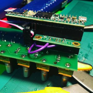
    My original experiments were with a Teensy 3.2, but its rather limiting 64k of memory meant I only had about half a second of audio buffer. I’ve now moved to using the Teensy 3.6, which has a whopping 256k of ram! I’ve also implemented 12-bit audio (2 samples stored in 3 bytes), which gives me an audio buffer of around 3 seconds, which is enough to get nice repeating loop effects. I’m using the PCB board I designed for my AudioFreeze project which was designed for Teensy 3.2. The 3.6 is twice the length, but by crafting a tower block of female header I was able to raise the Teensy over the height of the ribbon power connector.


    img_0919


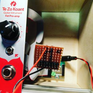
    Initially I had a very peculiar issue where the module would only work when powered by USB, not when in the modular case. Weirdly, when I was putting the multimeter on it, to test power was getting to the board (which it was), it would sometimes startup, and then work fine. It turned out the case wasn’t supplying enough current. The Doepfer power board only supplys 50mA on the 5V rail, and 100mA on the 12V rail. I tried making a small add-on board with a voltage regulator on, so I could you the 12V power, but it still wasn’t enough. I ended up adding a separate power board, and powering it with a 5V wall adapter directly.


    img_0937


    With all the extra processing power the 3.6 provides I was able to create 3 separate play heads, all looping audio at different pitches which is mixed together. One plays at 1/2 speed (1 octave down), one at normal speed, and one at double speed (1 octave up). Currently the mix ratios of these are fixed as I’ve run out of knobs on my board!

    Here’s a very simple demo, you can hear the acoustic sound of the guitar in this video, normally I’d want the effect to be totally wet, but it does serve to show you what the original audio is doing..


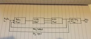
    This diagram shows how the processing blocks are organised. It’s the glitch delay block that’s really doing all the work.


    I actually played with this live at my last gig at Spirit of Gravity. I hope to incorporate it into my material more when I’ve properly learnt to play it! Next up, I may try to add CV control to all the parameters. I’d also like to move away from using the audio shield, as I’m not really taking advantage of the 16-bit DACs/ADCs. I’m really only using it so I can use the Teensy ADC to read the pots. I’m planning on designing a new PCB and using a PIC chip to handle all of the pots and CV interface stuff and then connect that to the Teensy via I2C, but I’ve no experience of that, so that’s a whole new adventure!


    fullsizerender


    As always, code is here
  • Work in progress Glitch Delay

    So I’ve been beavering away on a new Eurorack effect based on the Teensy board again!

    Added a very rough demo, which starts with a dry loop, then entirely wet glitch effect. Dials from top to bottom are

    1. Glitch window size
    2. Glitch window speed
    3. Feedback
    4. Dry/Wet mix


    The effect is sort of a cross between my previous AudioFreeze project and a digital delay. Is consists of a delay line with a write head and a read head. The difference being the read head is basically looping a tiny buffer behind the write head. This is implemented using 2 read heads which crossfade between each other to avoid popping. The window (the size of which is controlled by pot 1) moves (forwards only currently due to lack of buffer size) through the buffer at a speed controlled by pot 2. There’s a certain element of randomness added too each time the loop restarts. It then has to jump over the write head as it cycles through the buffer.

    Next stage is to extend the buffer time by adding more memory chips to my Teensy based board. I should hopefully be able to extend the time time from ~0.5s to around ~7s. This should give a lot more time to hear glitches repeat before the write head loops back around and the play heads have to skip over it.

    https://github.com/cutlasses/GlitchDelay


  • Build your own AudioFreeze

    I’ve added the Gerber files to GitHub so anyone can build the module if they like. As a disclaimer this module should be seen as a prototype. IT HAS NO POWER FILTERING OR SHORT CIRCUIT PREVENTION, if you plug the ribbon cable in the wrong way you may damage the board and potentially your other modules. Also your case must supply 5V power (some don’t). As this was my first PCB I wanted to make it as simple as possible. I’m merely making it available as a resource for people who want to make their own boards. If you do build your own I’d love to see it. Please tweet me @scolar any pictures or videos!

  • AudioFreeze Fascia complete

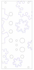
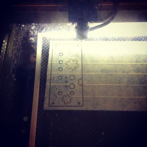
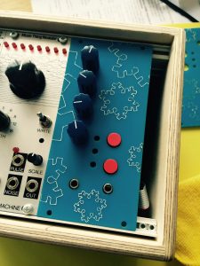
    To be able to mount my AudioFreeze PCB in a modular case I needed to craft a fascia. I decided to use laser-cut acrylic. I haven’t found anywhere in the UK that does bespoke Aluminium cutting, and, due to a kind friend, I had access to a laser cutter! I created a vector image in InkScape, a free, well-featured vector art package. It does have its drawbacks though, it’s not particular user friendly. I haven’t found an easy way to show the centre of objects, so I ended up making guidelines to show me, and hiding them in another layer.

    I came up with a design involving snowflakes, and I wanted these to be in a different colour. I covered the acrylic in masking tape, and once it was cut I painted over the top with several layers of thin acrylic paint. It wasn’t entirely successful, the paint didn’t fill the etched areas quite as well as I’d hope, but I’m still very pleased with the final result. One downside of using acrylic is that it’s 3mm thick, which seemed slightly too deep to be able to get a nut on the jack sockets as not enough of the barrel protruded. The Aluminium panels from the Thonk – Music Thing kits I’ve built were thin enough not to have this problem.

    I’ll make another demo video soon..


    Screen Shot 2016-06-18 at 18.47.58
    Vector image for laser cutting


    IMG_0573
    Laser cutting the masking taped acrylic


    Painting onto the fascia
    Painting onto the fascia


    IMG_0576
    Finished article!
  • AudioFreeze Prototype built

    After a few hours of soldering my PCB is populated and it works! There was no way of knowing for sure without building it, and as this was my first PCB I had some doubts, but thankfully it’s all good. The LEDs and corresponding resistors have yet to be added, I wanted to wait for the facia before soldering these in place to get the height right  It can be powered either via USB or from the 5V line on the Eurorack connection.

    First version of the firmware is up on GitHub. Current version has only one mode. Top red button captures a loop of audio. Pots from top to bottom control:-

    • loop window size
    • loop window position
    • pitch
    • mix with incoming audio

    Bottom red bottom currently doesn’t do anything, but my plan for the next version of the firmware is to have multiple modes. I’m thinking of a mode which has a volume based threshold for triggering the sampling, and possibly a granular delay mode. Also the ability to sample in 8 bit (rather than 16 bit) for increased loop time. LEDs are also unused currently, they will probably show active modes.

    Next up is the fascia, hopefully laser cutting that this week so expect pictures soon.

    A photo posted by @scottpitkethly on

    A video posted by @scottpitkethly on

  • PCBs have arrived!

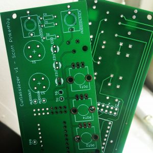
    My first ever PCBs have arrived, possibly the first of many? Can’t wait to get the first one soldered up. After that I need to design the Eurorack panel, current plan is laser cut acrylic. Will post demos as soon as it’s made! Thanks to Hackvana for fabricating them, a highly recommended service!


    IMG_0433

  • Making PCBs

    So, I’m ready to progress with my AudioFreeze project, and move from breadboard prototype to permanent module. I didn’t relish the thought of transferring the circuit to Vero board, it would be possible but fiddly. I toyed with the idea of fabricating my own (see http://www.instructables.com/id/How-to-Etch-a-PCB/), but a friend made me aware that you can get very low (10 or so board) runs of unique PCB designs factory manufactured for around £25, so roughly £2.50 a board.

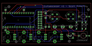
    I downloaded Eagle Light Edition, PCB CAD software. It’s free for non-commercial hobbyists to use (with a maximum board size 100mm x 80mm, which is fine for my needs). To say it has a steep learning curve is an understatement, its UI is rather non-standard, thankfully I had someone very patient to mentor me and get me started (thanks Jason!)

    It took me a couple of iterations, but the board design is now finished, let’s hope it works! Just a 3 week agonising wait for them to be delivered from Hong Kong!


    Screen Shot 2016-05-28 at 11.53.30 Screen Shot 2016-05-28 at 11.53.06

  • MIDI pedal complete!

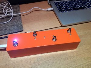
    After some soldering and drilling I’ve finished the final version of my MIDI pedal. I’m really pleased with how it’s turned out. I’ve used it live now, and it was really handy having LEDs to show which pedals I had active, and I can now control Ableton’s looper more accurately. I’m less convinced by the usefulness of the MIDI clock LED flash, it’s in equal amounts useful and distracting. Never mind, it’s easy to disable in code if I choose.

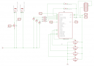
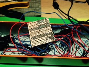
    I tried to make the layout of my breadboard prototype as close as possible to the layout I was going to use on the Veroboard. Soldering this together was pretty straightforward, and although it looks a little untidy it worked first time (ok, second time, I had to solder suck some of the solder from one of the joints as it was connecting 2 rails together).

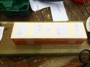
    The build went reasonably smoothly. I used InkScape to create a drilling schematic. The only problem was I didn’t factor in the size of the components (only the size of the drill holes), meaning it was only by chance that the bodies of the potentiometers didn’t overlap the USB port – phew! I then marked each centre point with an awl, before drilling a small pilot hole, and then cutting the desired hole size with the hole cutter. This may well be the de-facto drilling technique, not sure, but it worked for me.


    Pre-drilling
    Pre-drilling
    guts
    Guts!
    finished
    Finished article


    The code is now slightly more complex. LEDs can be paired together allowing the activation of one to toggle the state of another (called a sister pedal in the code). This is because 2 of my pedals control the activation of the ‘Record Arm’ on 2 audio tracks that output to the same channel on my Audio Interface (basically 2 different guitar amps, which can play simultaneously but only one can be receiving audio). Activating one ‘Record Arm’ disables the other.

    Code available on GitHub https://github.com/cutlasses/MidiPedal

  • MIDI pedal prototype complete

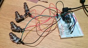
    The prototype of my USB MIDI pedal is now complete. What you see below is prototyped on breadboard using the TEENSY development board, running software which I wrote in C/C++. It has 4 fully programmable pedal switches (either toggle or momentary), and an LED which flashes in time with the midi clock. This clock LED is to enable me to record loops without the need for headphones (I have not actually tried doing this). The next stage will be to solder it up on veroboard and build the housing. The enclosure has arrived, just need to do some drilling!


    Once this is finished I’ll have more control over my live performance. My previous MIDI pedal was not programmable, and therefore I was somewhat restricted. With this I’ll be able to have more control over my live looping.


    breadboard
    Prototype on breadboard
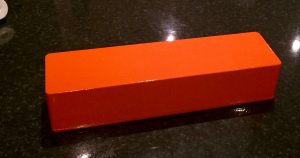
    Enclosure
    Painted aluminium enclosure


    Here’s the source code for those interested.

    #include 
    
    #define MIDI_CHANNEL        1
    #define MIDI_CLOCK          248
    #define MIDI_START          250
    #define MIDI_CONTINUE       251
    #define MIDI_STOP           252
    #define PULSES_PER_QUARTER  24
    
    #define NUM_PEDAL_SWITCHES  4
    
    #define MIDI_CLOCK_LED      4     
    
    #define BOUNCE_TIME         10
    
    int midi_counter(0);
    
    struct PEDAL_SWITCH
    {
      int                   m_pedal_pin;
      int                   m_led_pin;
      int                   m_midi_cc;
      bool                  m_is_toggle;
      bool                  m_active;
    
      Bounce                m_bounce;
    
      PEDAL_SWITCH( int pedal_pin, int led_pin, int midi_cc, bool is_toggle ) :
        m_pedal_pin( pedal_pin ),
        m_led_pin( led_pin ),
        m_midi_cc( midi_cc ),
        m_is_toggle( is_toggle ),
        m_active( false ),
        m_bounce( pedal_pin, BOUNCE_TIME )
      {
      }
    };
    
    PEDAL_SWITCH pedals[ NUM_PEDAL_SWITCHES ] = { PEDAL_SWITCH( 0, 5, 16, true ),
                                                  PEDAL_SWITCH( 1, 6, 17, true ),
                                                  PEDAL_SWITCH( 2, 7, 18, true ),
                                                  PEDAL_SWITCH( 3, 8, 19, false ) };
    
    void setup()
    {
      pinMode( MIDI_CLOCK_LED, OUTPUT );
      
      for( int i = 0; i < NUM_PEDAL_SWITCHES; ++i )
      {
        const PEDAL_SWITCH& pedal = pedals[i];
        
        pinMode( pedal.m_pedal_pin, INPUT_PULLUP );
        pinMode( pedal.m_led_pin, OUTPUT );
      }
      
      usbMIDI.setHandleRealTimeSystem( midi_real_time_event );
    
      midi_counter = 0;
    }
    
    void midi_real_time_event( byte data )
    {
      switch( data )
      {
        case MIDI_CLOCK:
        {
          ++midi_counter; 
      
          if( midi_counter == PULSES_PER_QUARTER )
          {
            midi_counter = 0;
            digitalWrite( MIDI_CLOCK_LED, HIGH );
          }
          else if( midi_counter == PULSES_PER_QUARTER / 2 )
          {
            digitalWrite( MIDI_CLOCK_LED, LOW );
          }
    
          break;
        }
        case MIDI_START:
        case MIDI_CONTINUE:
        {
          midi_counter = 0;
          
          digitalWrite( MIDI_CLOCK_LED, HIGH );
    
          break;
        }
        case MIDI_STOP:
        {
          digitalWrite( MIDI_CLOCK_LED, LOW );
          
          break;
        }
      }
    }
    
    void loop()
    {
      usbMIDI.read();
    
      for( int i = 0; i < NUM_PEDAL_SWITCHES; ++i )
      {
        PEDAL_SWITCH& pedal = pedals[i];
    
        pedal.m_bounce.update();
    
        if( pedal.m_bounce.fallingEdge() )
        {
           /*Serial.print("pedal down ");
           Serial.print(i);
           Serial.print("n");*/
    
           if( pedal.m_is_toggle )
           {
            pedal.m_active = !pedal.m_active;
           }
           else
           {
             pedal.m_active = true;
           }
    
           usbMIDI.sendControlChange( pedal.m_midi_cc, 127, MIDI_CHANNEL );
        }
        else if( pedal.m_bounce.risingEdge() )
        {
          /*Serial.print("pedal up ");
          Serial.print(i);
          Serial.print("n");*/
    
          if( !pedal.m_is_toggle )
          {
            pedal.m_active = false;
    
            usbMIDI.sendControlChange( pedal.m_midi_cc, 0, MIDI_CHANNEL );
          }
        }
    
        if( pedal.m_active )
        {
          digitalWrite( pedal.m_led_pin, HIGH );
        }
        else
        {
          digitalWrite( pedal.m_led_pin, LOW );
        }
      }
    }
    
  • MIDI Controller Stage 2

    It works! I had made a couple of foolish errors, due to looking at the wrong pin schematic for the TEENSY (I have 3.2 not 2). But I now have a working, single pot controller. With this mastered I’m hoping that adding more pots should be straight forward. I’d also like to include an LED that flashes on the MIDI clock, this should help me keep time without the need for headphones.

    I was impressed at the simplicity of the coding for TEENSY. The snippet below is the entire code. I’m having to smooth the value to reduce noise. Apparently the inclusion of a capacitor will help reduce this.

    Looking forward to designing a case..


    #define NUM_PORTS           1
    int values[NUM_PORTS][2];
    
    void setup()
    {
    
    }
    
    void loop()
    {
    
     for( int i = 0; i < NUM_PORTS; ++i )
     {
       const int prev_value    = values[i][0];
       const int current_value = values[i][1];
       int new_value           = analogRead( A0 ) / 8;
    
       int blended_value       = ( new_value + current_value + prev_value ) / 3;
    
       if( prev_value != blended_value )
       {
         Serial.print("analog 0 is: ");
         Serial.print(blended_value);
         Serial.print("n");
    
         usbMIDI.sendControlChange( 1, blended_value, 1 );
       }
    
       values[i][0]             = current_value;
       values[i][1]             = blended_value;
     }
    
     delay(5);
    
    }